
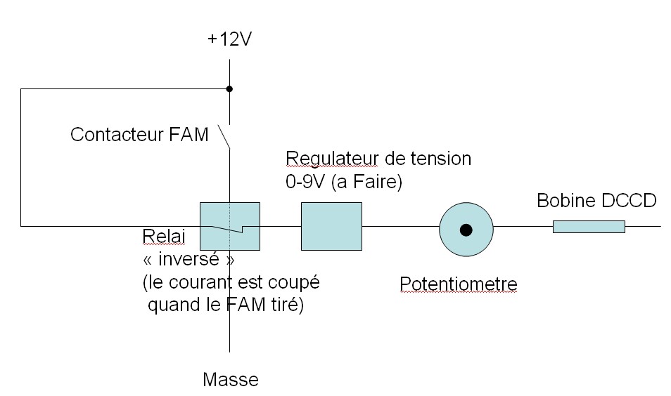
Le \"régulateur\" n'est pas obligatoire mais ca permettra de pas dépasser les 9V.
apres on peut envisager un \"voltmetre ( leds pourquoi pas) pour afficher le \"taux de blocage\"

Site consacré à la Subaru Impreza, une des dernières voitures de rallye homologuée pour la route.
Modérateurs : Moderateurs, Comité


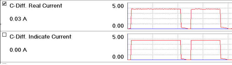
I was able to make my own DCCD controller out of spare parts I had laying around the lab. Basically, I reprogrammed an 8 bit microprocessor to read an analog input (potentiometer) and spit out a 150Hz square wave that varies the duty cycle between 0% and 100% (based on potentiometer voltage).
I read in a 0V to 5V signal from the potentiometer . The percentage of this voltage (compared to 5V) is directly transferred to the output compare register which in turn operates the PWM 12 volt output (pulse width modulated). At zero volts input signal, the output has a duty cycle of 0%. At five volts input signal, the output has a duty cycle of 100%.
The '06 dccd documentation indicates that there is a mechanical slip limiting clutch in addition to the electronically actuated clutch. It goes on to say that this mechanical clutch governs the regime of 0-30% lockup, with the electronic clutch covering the remaining 30-100%. It implies that you can do nothing to prevent the 0-30% lockup, this will always occur whenever differential rotation of the front & rear driveshafts is attempted (i.e. there is no totally \"open\" behavior available in the '06 center diff).
The controls allow you to manually pre-select the behavior between 30-100% lockup, but the resulting lockup behavior is only induced when differential rotation is attempted (loss of traction on one axle occurs).
alambrik a écrit :Peut etre une piste pour le signal :I was able to make my own DCCD controller out of spare parts I had laying around the lab. Basically, I reprogrammed an 8 bit microprocessor to read an analog input (potentiometer) and spit out a 150Hz square wave that varies the duty cycle between 0% and 100% (based on potentiometer voltage).
I read in a 0V to 5V signal from the potentiometer . The percentage of this voltage (compared to 5V) is directly transferred to the output compare register which in turn operates the PWM 12 volt output (pulse width modulated). At zero volts input signal, the output has a duty cycle of 0%. At five volts input signal, the output has a duty cycle of 100%.
Il n'y a pas besoin de Microprocesseur et controleur pour faire ça
un vulgaire ampli Op monté en ocillateur + quelques résistances et condo + un Transistor de puissance et le tour est joué (seul nous manque la tension de pilotage)


Je parle pour des GT et des STI de 2003, apres je ne connais pas pour les années suivante
Revenir vers « Transmissions »
Utilisateurs parcourant ce forum : Aucun utilisateur inscrit et 2 invités

